Didn't say this earlier, but the coaxes are ser# 125 and 128. The woofers are 0575 and 0576 consecutive numbers. The measured T/S are very tight comparitively, save for the tweeters' Fs being ~100Hz different.
The mid chambers were lined with the Woolous adhesive felt and nothing more. There just was not room to fit anything else in there.
Thus far I have one complaint. IMO, the tweeter terminals being mounted where they are on that lower frame post is not very congenial for its connections. I had to shave the corners from it for easier fitment in the round chamber. If I could suggest a better place for them, I'd suggest the major frame supports. That way, the connection would have plenty of room and not have to be on a flimsy post or be physically hindering the mounting process. That said, it's a minor complaint, and I just dealt with it. I just feel the terminal relocation would make mounting it easier.
Looked through my parts tonight, and I likely have everything I need to mock these filters up. We'll see what the actual measurements show...
On axis measurements are done for xover simulation. Cabinets are currently fully assembled and finished pending baffle removal for xover installation.
Data dump coming, so this will be very long...
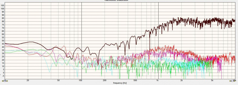
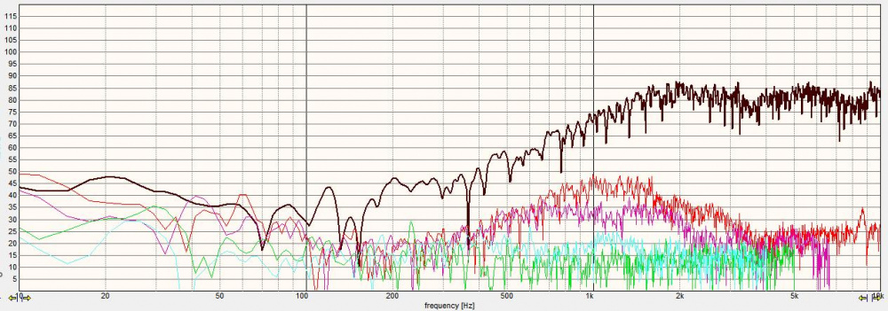
Tweeter:
Obviously, the HD rises below 3.5k, so my xover point that fell into place before will likely stick. The dip at 12k will likely disappear off axis as most coaxial drivers improve at 10-15 deg off axis horizontally. The dip at 3.5k will just help with the rolloff. While it is not exceptionally flat as far as tweeters go, it really isn't awful response. A little lift in the top end will allow the off-axis to be flat.
The HD is about -55dB at tentative xover point, and only rises to just below -47dB at the spike. This is VERY low HD as far as the masses go, and should not be audible.
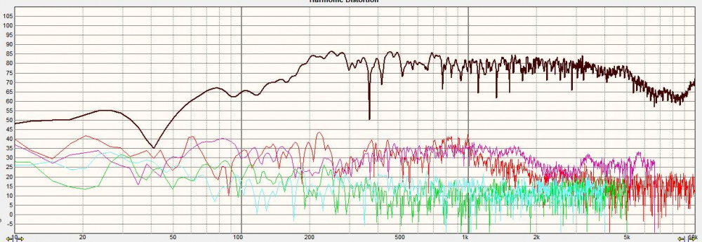
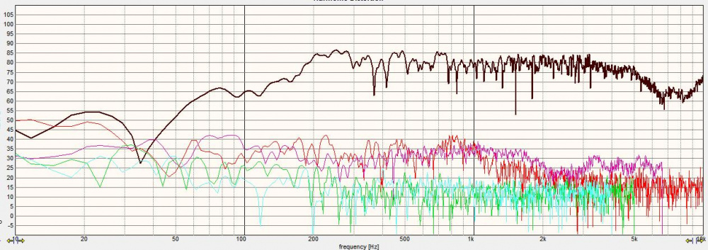
Midrange:
I am pleased that the breakup peak is not as prevalent in actual measurements as it is in the datasheet. The response above about 250Hz is pretty flat to the upper natural rolloff. These 2 points should make the midrange xover much easier.
Unfortunately, the 3rd order HD runs through along with the 2nd order HD at about the same magnitude for the intended bandwidth, and is higher than the 2nd from 1k-2k. The later rise in 3rd order will be suppressed by the rolloff and likely be of no concern. This all said- the relative HD is at -40dB for 2nd order and -45dB or lower from the fundamental for 3rd order, and is at about 0.8-1% and likely close to inaudible. I feel this is pretty good even if not quite state of the art. I've worked with lesser drivers and still liked them just fine. I have no worries here.
I have yet to remeasure the impedance mounted in the chamber, but I will say this; The bump at 250Hz is legit, noisy, buzzy, and resonant garbage that I am glad will be out of bandwidth by crossing an octave above it. Just like Tweeters' Fs spike makes them buzz in male vocals if not tamed, this is doing the exact same thing but lower in fundamental. If someone were to use this as a sole driver in a 2way, I do not feel this would be a problem any longer. It is purely an applied result of how I am using it. In sim, the 8 ohm shunt resistor nuked the spike, so it should be easy to remove.
Woofer:
What can I say except that if you have not heard and experienced an 1139, you are missing out! It does what it does and does it well, even if you need to give it some juice to get there. I bet I've used this woofer a half dozen different ways, and it always makes me smile at its capabilities. They will soak up 75W continuously all day long, and simulated peak at that output in this box alignment is about 102dB, with an F3 of 40Hz while tuned to 47Hz. Tuning lower is more likely to be used as a subwoofer, or in a larger case like a floor stander. Xmax+15% is not breached until 30Hz at that output. I used a 2.5" diameter vent on purpose for the applied VersaBox for applications such as this when a lot of air is moving at higher outputs. Vent Mach is also below audibly noisy at this output due to the diameter applied.
It looks like I'll have to remove about 6dB from the mid, and 7-8dB from the tweeter to line them up. I did find a laminate core in the right value as prior simmed so I get less insertion loss of a fraction of a dB as opposed to the loss with a 0.5 ohm in series. Hoffman is strict, and saving what sensitivity I can is paramount. The dip at 175Hz is floor bounce. Usable output range is to about 300Hz before rolloff starts to roll into the midrange.
The HD on them is pretty much -30dB from reference or more below there for its entire bandwidth. For high excursion woofers that move a lot, this is just plain exceptional.
I forgot to snap an image of the second midrange, but it is virtually the same. The bump below 1k on the midrange is something I looked at a bit. It shows as the peak in HD on the midrange for sure, but ultimately is not strong enough to likely be of concern.
Well, shifted parts a bit: Added 10dB to all plots for visibility, trimmed headers, changed tails, traded one notch for another, forgot to change the DCR on the woofer coil, tried a 'Tude circuit on the mid to no avail (just was much worse alignment), and changed offsets to those measured. I managed to save/increase sensitivity a smidge.
The notch on the mid breakup was no longer needed, but needed a FULL NOTCH on it's cavity resonance instead. FR shows it is still present but reduced, so measurements will have to reveal the truth afterwards.
Funny you mentioned the woofer dip in FR is different than what the impedance sweep tells you the tuned frequency is.
Seems that when measuring the FR of a woofer and port, these didn't line up as well. The dip of the woofer was lower than the peak of the port. Still haven't figured that one out. Only thing I could find is a page by D'Appolito stating "First, the sharp dip in woofer response indicates the tuning frequency of the vented enclosure. In general, this value is more accurate than one obtained from the impedance curve, since it is not corrupted by voice coil inductance."
But why the dip and peak of the woofer and port don't line up is still in question. Anyone else notice this before?
Sorry to hijack, Ben, but your comment reminded me of this.
I've seen it before too, always taking the FR as more accurate if I had it, but not really knowing why 3 different measurements come out with different answers.
It appears the xover points from this more recent sim with real data are now 475 and 3.8k, so the mid is getting a bit more bandwidth.
Just as a note, this is still my method of seeing where the points fall on their own, while keeping HD low, and flat response with good impedance, and trying not to go overboard on parts unless deemed absolutely necessary. Jeff called it a 'holistic' method. I did not really select a xover initially and try to make that work by brute force. The targets were only used as an alignment shape to get in the ballpark, and then adjusted to the outcome for visuals. It is easier to let the drivers work as they do, and to the designer's advantage.
Did some more fiddling when searching the parts stash for xover assembly, as I had to adjust the DCR of the coils being used. I removed the resistor on the midrange notch, and just allowed it to use the DCR of the 3.0mH. This really tanked the bump, and should no longer be a problem. I will listen with the highpass and notch alone to see if it is still audible. The impedance rises back up due to the highpass cap and remains stable as a whole. The LC inherent does not cause any low impedance problems because of this.
I'll post an update of the circuit as it sits after measurement and voicing confirmation.
Muhaahahahh....
I'm running them in right now mocked external. Same tweeter pad, but reduced mid a touch. Very clean and solid sound, cohesive in all areas, and good detail. I'll get the mic on them later....
Mostly what I had handy. Happened to be 12awg coils for the mid, SuperQ for the woofer, and a 14awg air for the tweeter. Used a Solen 100uF on the woofer, ASC oil series and Solen Silver shunt on mids, and a Fostex copper/tin foil on the tweeter. Yeah, some serious retail coin in these.
The foils came from a buyout Chuck and I did some time ago from another builder. The SuperQ were either a windfall item, a Tent Sale find, or a buyout box I bought from Rick Craig awhile ago, got the 10uF Solen Silver cheap from him too. I bought the ASC last week new. The Fostex were on closeout from Mad a bit ago. The Solen 100uF I got in a windfall from another builder.
It may not look like it, but I'm pretty thrifty too. Yes, these are made to fit internally in the cabs too.
No, no windows this time. No place for it to go anyway. I really like the ASC X386 (round) or X387(oval) caps. They always yield a spaciousness around the mids, good detail, and I've used them for this many times. I still have them as the highpass in my Attitudes build, and used them in the Drottnar more recently. RS components, formerly Allied Electronics, has the best prices I've found for them. They come in various voltages from 250 to 440, and are polypropylene bathed in a kind of vegetable oil. It sloshes around when you shake them. For reference, these were about $15 each and are 20uF, so not that expensive. Highly recommended!
Just for a size reference, the main xover board is 6"x7", and the thickness of the structure is 4.25". I bet it weighs 4-5#. 5 caps, 5 coils, and 2 resistors. 12 parts is not bad for a 3way.
PS- The little green mylar cap on the ASC is to trim for value. I've done the same thing before with no issues. However, Russian polystyrenes as trim caps made the Drottnar sound broken. YMMV.
Okay, measurements are done and voicing is verified.
I tried to import the horizontal axes plots into Omnimic like Nick did for the Napoleon/Cavalry combo, but it said 'load failed'. I then used Xsim to do the same thing, so it's not as pretty. I've had to strip headers to use them in that software or any other I've used in the past, so maybe that is why Omnimic refused. It's funny that the software that generated the files with the headers added won't open them?
I was able to get the voltage to vary between 2.8 and 3.0 volts to yield an approximate sensitivity of ~80-82dB range as a best fit.
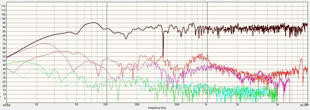
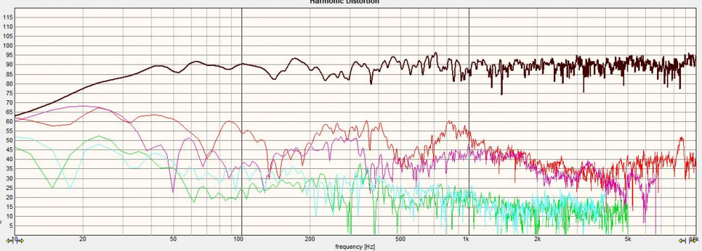
The 150Hz dip is floor bounce, and the 60-80Hz on the right could be a room mode, but these are gated anyway and should not be taken seriously below about 500Hz.
The midrange HD is the outlier in finale, and 2nd order HD peaks twice at -30 to -35dB. The 3rd order is below 1% and of no concern. Even with the 2nd order (pleasing even order) a touch higher than some others, they do sound quite good. The high Q issue at 198Hz is no longer of concern.
The other thing I found interesting is that the tweeter dip commonly found in the top octave seems to be reduced or subdued in depth magnitude compared to what I initially measured. Listening at both 0 degrees and 15 degrees seems to both be okay and of no consequence.
Right speaker:
Left speaker:
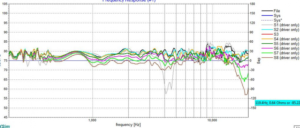
Right speaker horizontals are below. I just kept twisting the speaker and guessed at the relative angle. They should be close. I was amazed that the rolloff didn't start in until 60 degrees off axis. I included the inverted midrange for the info it has in grey.
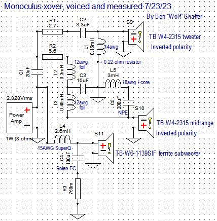
And then I drew the Final Voiced schematic in Xsim while I was there. I misspoke in my last post here and said 12 parts. It is actually 13 parts, and I forgot a resistor was there. Notice I did use the cascaded connection method with the large series highpass capacitor before both midrange and tweeter. Xover points are Approximately 400Hz and 4kHz.
I have to say I am pretty surprised at how good these sound. I keep coming back to 'cohesive' as the main thought in description. I have to solder leads onto the xover, mount and solder the correct resistors into place, and install them inside the cabinets before I am finished.
Thank you for following along. I will take better photos of the xovers and project in the near future as I'm buttoning them up to post for visuals.
...and I might make one more level adjustment. The last few builds it seems that I've added an ohm or less to the series resistance. I added a 0.5 ohm to the 20uF cap to make the fatigue in long and moderate listening to go away. I didn't notice it as first, that is why living with a project is better than calling it good after a couple hours. What's funny, is that this might be too much added currently.
I initially started with the 6 ohm and 2.7 ohm values. I felt that was not enough output on the coax. Bass was extra heavy.
I changed to 5.6 and 2.2 ohms, but felt the tweeter was too much and bright. I backed it down to 2.7 ohms and verified with the measurements you see above. Very flat as that sits. Bass seemed balanced with mids and highs.
Fatigue set in as stated, and complemented with the 0.5 to effectively be 6.1 and 3.2 ohms. I have 6 ohms and 3 ohms on the alligator jumpers, so that is my next stop to reduce padding just a hair. I will double check and measure resistor values to make sure I know absolute values, but I bet 5.8 and 3 ohms will be the result.
Wolf,
Thanks for posting your Xovers, and changes post listening. It is very educational as I try to duplicate your crossovers on VituixCAD, and pick up an idea or two.
I would not think I would be likely either, but you never know.
I cascaded the midrange cap for more tweeter protection. I'm not sure what you mean by 1st order series, as this is a parallel xover. I'm glad this has been beneficial for you.
I think I have it nailed, but I'm going to listen a lot more before posting something short of the best.
I fiddled with a brighter recording and got it sounding good, then slowly brought the tweeter back up. I also had a hunch that the tweeter Fs was making some buzz. So, yes, I added a resistor across the tweeter for this possibility. It seems to have helped the issue, even though the Z magnitude is already low by use of ferrofluid. When done with the bright music, I popped in a better recorded disc for absolute spectral balance. I then played with the mid pad, and decided the 5.6 ohm is where it has sounded best over all, every time. I ended up reducing the tweeter series pad to complement the new shunt resistor with the same output for the better recorded music. The treble just seems better and less fuzzy. I switched back and forth between it and another disc as I have 2 players in the rack. I must note that I have heard these recordings on almost every pair I've built, or at least on the speakers I've built since the albums were released. I found myself getting lost in the 3rd one, and swayed with eyes shut on the couch for the catchier tunes. I was moved emotionally too a few times. That's when I knew I found the proper balance. I wasn't listening to the speakers any longer, but fully enjoying the music.
Recordings used:
Sarah Bareilles - Live at the Variety Playhouse (Bright)
Jennifer Warnes - The Hunter (Well recorded)
Kathy Troccoli - Corner of Eden (Another good recording)
I have to hit them with some metal and rock yet again to make sure they hold up like I prefer, but I am hopeful. I really did a lot of critical listening today after work, and I'm very ready for the pillow....
Comments
Didn't say this earlier, but the coaxes are ser# 125 and 128. The woofers are 0575 and 0576 consecutive numbers. The measured T/S are very tight comparitively, save for the tweeters' Fs being ~100Hz different.
The mid chambers were lined with the Woolous adhesive felt and nothing more. There just was not room to fit anything else in there.
Thus far I have one complaint. IMO, the tweeter terminals being mounted where they are on that lower frame post is not very congenial for its connections. I had to shave the corners from it for easier fitment in the round chamber. If I could suggest a better place for them, I'd suggest the major frame supports. That way, the connection would have plenty of room and not have to be on a flimsy post or be physically hindering the mounting process. That said, it's a minor complaint, and I just dealt with it. I just feel the terminal relocation would make mounting it easier.
Looked through my parts tonight, and I likely have everything I need to mock these filters up. We'll see what the actual measurements show...
InDIYana Event Website
On axis measurements are done for xover simulation. Cabinets are currently fully assembled and finished pending baffle removal for xover installation.
Data dump coming, so this will be very long...
Tweeter:


Obviously, the HD rises below 3.5k, so my xover point that fell into place before will likely stick. The dip at 12k will likely disappear off axis as most coaxial drivers improve at 10-15 deg off axis horizontally. The dip at 3.5k will just help with the rolloff. While it is not exceptionally flat as far as tweeters go, it really isn't awful response. A little lift in the top end will allow the off-axis to be flat.
The HD is about -55dB at tentative xover point, and only rises to just below -47dB at the spike. This is VERY low HD as far as the masses go, and should not be audible.
Midrange:


I am pleased that the breakup peak is not as prevalent in actual measurements as it is in the datasheet. The response above about 250Hz is pretty flat to the upper natural rolloff. These 2 points should make the midrange xover much easier.
Unfortunately, the 3rd order HD runs through along with the 2nd order HD at about the same magnitude for the intended bandwidth, and is higher than the 2nd from 1k-2k. The later rise in 3rd order will be suppressed by the rolloff and likely be of no concern. This all said- the relative HD is at -40dB for 2nd order and -45dB or lower from the fundamental for 3rd order, and is at about 0.8-1% and likely close to inaudible. I feel this is pretty good even if not quite state of the art. I've worked with lesser drivers and still liked them just fine. I have no worries here.
I have yet to remeasure the impedance mounted in the chamber, but I will say this; The bump at 250Hz is legit, noisy, buzzy, and resonant garbage that I am glad will be out of bandwidth by crossing an octave above it. Just like Tweeters' Fs spike makes them buzz in male vocals if not tamed, this is doing the exact same thing but lower in fundamental. If someone were to use this as a sole driver in a 2way, I do not feel this would be a problem any longer. It is purely an applied result of how I am using it. In sim, the 8 ohm shunt resistor nuked the spike, so it should be easy to remove.
Woofer:

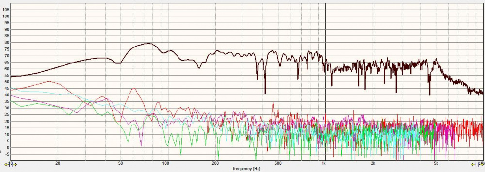
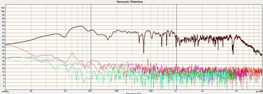

What can I say except that if you have not heard and experienced an 1139, you are missing out! It does what it does and does it well, even if you need to give it some juice to get there. I bet I've used this woofer a half dozen different ways, and it always makes me smile at its capabilities. They will soak up 75W continuously all day long, and simulated peak at that output in this box alignment is about 102dB, with an F3 of 40Hz while tuned to 47Hz. Tuning lower is more likely to be used as a subwoofer, or in a larger case like a floor stander. Xmax+15% is not breached until 30Hz at that output. I used a 2.5" diameter vent on purpose for the applied VersaBox for applications such as this when a lot of air is moving at higher outputs. Vent Mach is also below audibly noisy at this output due to the diameter applied.
It looks like I'll have to remove about 6dB from the mid, and 7-8dB from the tweeter to line them up. I did find a laminate core in the right value as prior simmed so I get less insertion loss of a fraction of a dB as opposed to the loss with a 0.5 ohm in series. Hoffman is strict, and saving what sensitivity I can is paramount. The dip at 175Hz is floor bounce. Usable output range is to about 300Hz before rolloff starts to roll into the midrange.
The HD on them is pretty much -30dB from reference or more below there for its entire bandwidth. For high excursion woofers that move a lot, this is just plain exceptional.
More to come...
InDIYana Event Website
InDIYana Event Website
Measured free air T/S and impedances:
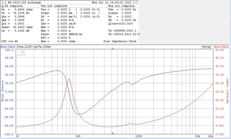
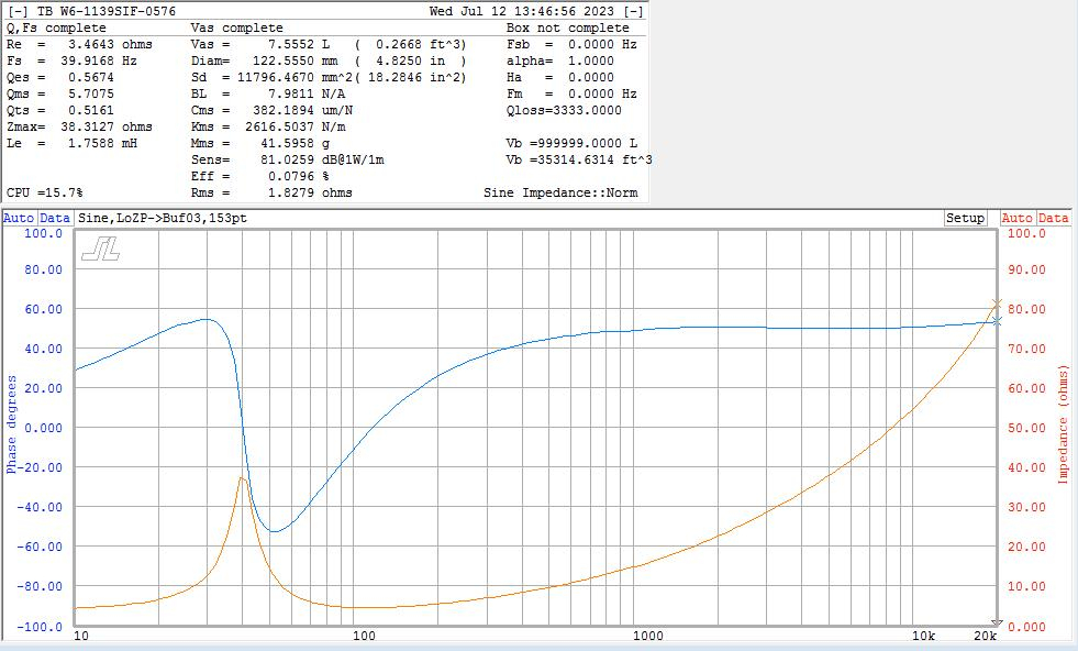
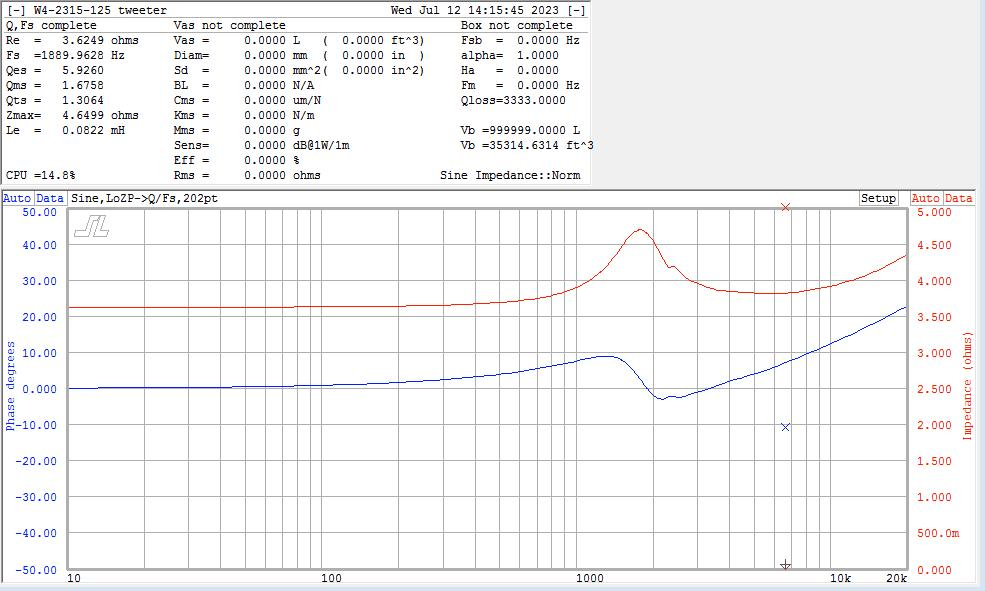
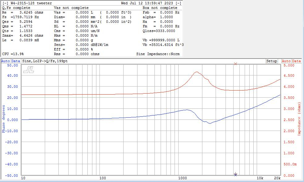
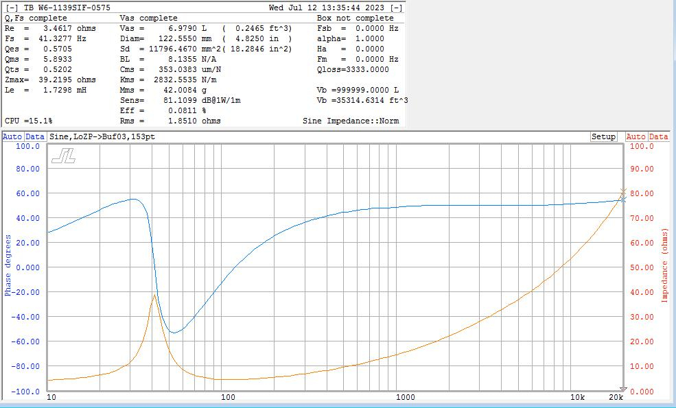
I forgot to snap an image of the second midrange, but it is virtually the same. The bump below 1k on the midrange is something I looked at a bit. It shows as the peak in HD on the midrange for sure, but ultimately is not strong enough to likely be of concern.
InDIYana Event Website
IN BOX impedances...
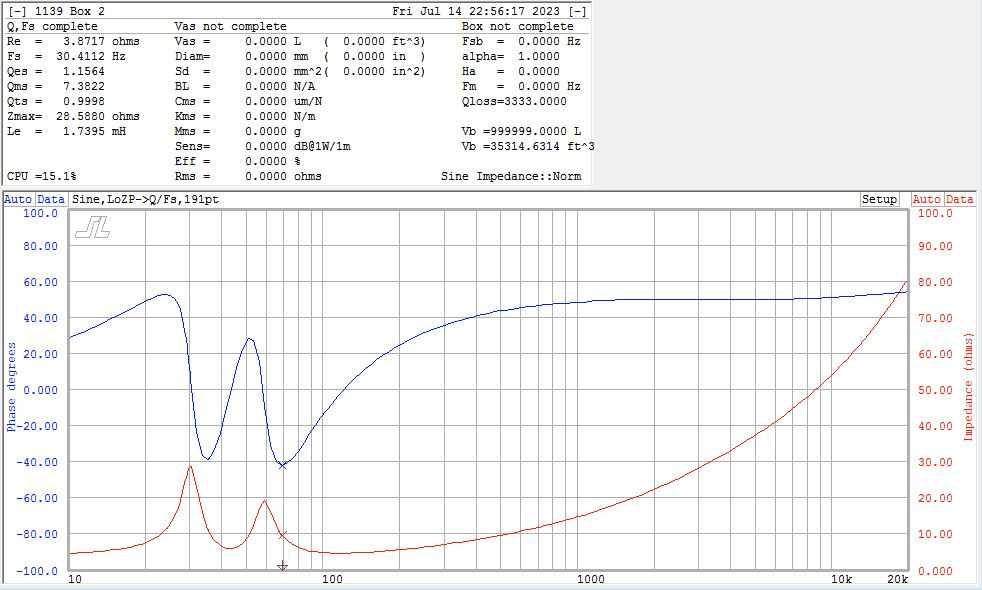
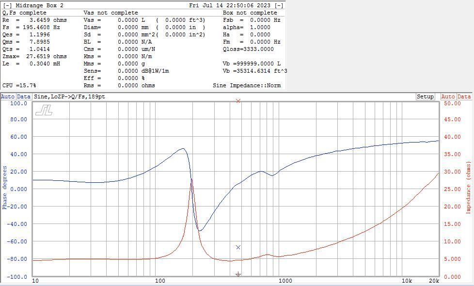
Cab2:
Cab1:
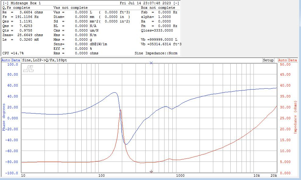
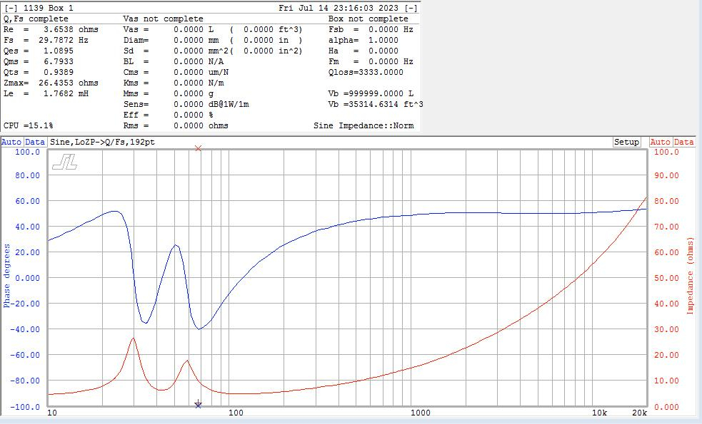
Funny that the dip in the woofer FR shows Fb = 47Hz, but the impedance shows it as Fb = 42Hz.
InDIYana Event Website
Well, shifted parts a bit: Added 10dB to all plots for visibility, trimmed headers, changed tails, traded one notch for another, forgot to change the DCR on the woofer coil, tried a 'Tude circuit on the mid to no avail (just was much worse alignment), and changed offsets to those measured. I managed to save/increase sensitivity a smidge.
The notch on the mid breakup was no longer needed, but needed a FULL NOTCH on it's cavity resonance instead. FR shows it is still present but reduced, so measurements will have to reveal the truth afterwards.
And away we go...
InDIYana Event Website
Funny you mentioned the woofer dip in FR is different than what the impedance sweep tells you the tuned frequency is.
Seems that when measuring the FR of a woofer and port, these didn't line up as well. The dip of the woofer was lower than the peak of the port. Still haven't figured that one out. Only thing I could find is a page by D'Appolito stating "First, the sharp dip in woofer response indicates the tuning frequency of the vented enclosure. In general, this value is more accurate than one obtained from the impedance curve, since it is not corrupted by voice coil inductance."
But why the dip and peak of the woofer and port don't line up is still in question. Anyone else notice this before?
Sorry to hijack, Ben, but your comment reminded me of this.
My measurements
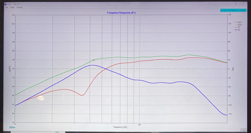
I've seen it before too, always taking the FR as more accurate if I had it, but not really knowing why 3 different measurements come out with different answers.
InDIYana Event Website
It appears the xover points from this more recent sim with real data are now 475 and 3.8k, so the mid is getting a bit more bandwidth.
Just as a note, this is still my method of seeing where the points fall on their own, while keeping HD low, and flat response with good impedance, and trying not to go overboard on parts unless deemed absolutely necessary. Jeff called it a 'holistic' method. I did not really select a xover initially and try to make that work by brute force. The targets were only used as an alignment shape to get in the ballpark, and then adjusted to the outcome for visuals. It is easier to let the drivers work as they do, and to the designer's advantage.
InDIYana Event Website
Thanks for the detailed writeup on your xover decision making process. I really learn alot from seeing how you deal with all the problems.
You are welcome, Bill! I'm glad it was useful.
InDIYana Event Website
Did some more fiddling when searching the parts stash for xover assembly, as I had to adjust the DCR of the coils being used. I removed the resistor on the midrange notch, and just allowed it to use the DCR of the 3.0mH. This really tanked the bump, and should no longer be a problem. I will listen with the highpass and notch alone to see if it is still audible. The impedance rises back up due to the highpass cap and remains stable as a whole. The LC inherent does not cause any low impedance problems because of this.
I'll post an update of the circuit as it sits after measurement and voicing confirmation.
InDIYana Event Website
Muhaahahahh....
I'm running them in right now mocked external. Same tweeter pad, but reduced mid a touch. Very clean and solid sound, cohesive in all areas, and good detail. I'll get the mic on them later....
InDIYana Event Website
costly looking litl Xover board - very nice
Mostly what I had handy. Happened to be 12awg coils for the mid, SuperQ for the woofer, and a 14awg air for the tweeter. Used a Solen 100uF on the woofer, ASC oil series and Solen Silver shunt on mids, and a Fostex copper/tin foil on the tweeter. Yeah, some serious retail coin in these.
The foils came from a buyout Chuck and I did some time ago from another builder. The SuperQ were either a windfall item, a Tent Sale find, or a buyout box I bought from Rick Craig awhile ago, got the 10uF Solen Silver cheap from him too. I bought the ASC last week new. The Fostex were on closeout from Mad a bit ago. The Solen 100uF I got in a windfall from another builder.
It may not look like it, but I'm pretty thrifty too. Yes, these are made to fit internally in the cabs too.
InDIYana Event Website
I initially saw the foils and then the Fostex. What can you tell us about the ASC oil series?
Tempted to put a clear back on these speakers- like an engine cover - of course not ideal - ha.
No, no windows this time. No place for it to go anyway. I really like the ASC X386 (round) or X387(oval) caps. They always yield a spaciousness around the mids, good detail, and I've used them for this many times. I still have them as the highpass in my Attitudes build, and used them in the Drottnar more recently. RS components, formerly Allied Electronics, has the best prices I've found for them. They come in various voltages from 250 to 440, and are polypropylene bathed in a kind of vegetable oil. It sloshes around when you shake them. For reference, these were about $15 each and are 20uF, so not that expensive. Highly recommended!
InDIYana Event Website
Just for a size reference, the main xover board is 6"x7", and the thickness of the structure is 4.25". I bet it weighs 4-5#. 5 caps, 5 coils, and 2 resistors. 12 parts is not bad for a 3way.
PS- The little green mylar cap on the ASC is to trim for value. I've done the same thing before with no issues. However, Russian polystyrenes as trim caps made the Drottnar sound broken. YMMV.
InDIYana Event Website
Yeah but will your air-conditioner start without that cap...
Okay, measurements are done and voicing is verified.
I tried to import the horizontal axes plots into Omnimic like Nick did for the Napoleon/Cavalry combo, but it said 'load failed'. I then used Xsim to do the same thing, so it's not as pretty. I've had to strip headers to use them in that software or any other I've used in the past, so maybe that is why Omnimic refused. It's funny that the software that generated the files with the headers added won't open them?
I was able to get the voltage to vary between 2.8 and 3.0 volts to yield an approximate sensitivity of ~80-82dB range as a best fit.

The 150Hz dip is floor bounce, and the 60-80Hz on the right could be a room mode, but these are gated anyway and should not be taken seriously below about 500Hz.
The midrange HD is the outlier in finale, and 2nd order HD peaks twice at -30 to -35dB. The 3rd order is below 1% and of no concern. Even with the 2nd order (pleasing even order) a touch higher than some others, they do sound quite good. The high Q issue at 198Hz is no longer of concern.
The other thing I found interesting is that the tweeter dip commonly found in the top octave seems to be reduced or subdued in depth magnitude compared to what I initially measured. Listening at both 0 degrees and 15 degrees seems to both be okay and of no consequence.
Right speaker:


Left speaker:
Right speaker horizontals are below. I just kept twisting the speaker and guessed at the relative angle. They should be close. I was amazed that the rolloff didn't start in until 60 degrees off axis. I included the inverted midrange for the info it has in grey.
And then I drew the Final Voiced schematic in Xsim while I was there. I misspoke in my last post here and said 12 parts. It is actually 13 parts, and I forgot a resistor was there. Notice I did use the cascaded connection method with the large series highpass capacitor before both midrange and tweeter. Xover points are Approximately 400Hz and 4kHz.
I have to say I am pretty surprised at how good these sound. I keep coming back to 'cohesive' as the main thought in description. I have to solder leads onto the xover, mount and solder the correct resistors into place, and install them inside the cabinets before I am finished.
Thank you for following along. I will take better photos of the xovers and project in the near future as I'm buttoning them up to post for visuals.
Simply put, I like these!
InDIYana Event Website
...and I might make one more level adjustment. The last few builds it seems that I've added an ohm or less to the series resistance. I added a 0.5 ohm to the 20uF cap to make the fatigue in long and moderate listening to go away. I didn't notice it as first, that is why living with a project is better than calling it good after a couple hours. What's funny, is that this might be too much added currently.
I initially started with the 6 ohm and 2.7 ohm values. I felt that was not enough output on the coax. Bass was extra heavy.
I changed to 5.6 and 2.2 ohms, but felt the tweeter was too much and bright. I backed it down to 2.7 ohms and verified with the measurements you see above. Very flat as that sits. Bass seemed balanced with mids and highs.
Fatigue set in as stated, and complemented with the 0.5 to effectively be 6.1 and 3.2 ohms. I have 6 ohms and 3 ohms on the alligator jumpers, so that is my next stop to reduce padding just a hair. I will double check and measure resistor values to make sure I know absolute values, but I bet 5.8 and 3 ohms will be the result.
More to come...
InDIYana Event Website
Wolf,
Thanks for posting your Xovers, and changes post listening. It is very educational as I try to duplicate your crossovers on VituixCAD, and pick up an idea or two.
I would not think I would be likely either, but you never know.
I cascaded the midrange cap for more tweeter protection. I'm not sure what you mean by 1st order series, as this is a parallel xover. I'm glad this has been beneficial for you.
InDIYana Event Website
Wolf,
When I get around to my build - I’ll post what I can and ANY thoughts/ suggestions/ ideas to try would be appreciated
Sure thing...
InDIYana Event Website
Looking forward to hearing these
Ditto.
Definitely one of your nicest builds yet, Ben. I'm sure they'll sound just as good as they look.
Thanks, guys!
InDIYana Event Website
I think I have it nailed, but I'm going to listen a lot more before posting something short of the best.
I fiddled with a brighter recording and got it sounding good, then slowly brought the tweeter back up. I also had a hunch that the tweeter Fs was making some buzz. So, yes, I added a resistor across the tweeter for this possibility. It seems to have helped the issue, even though the Z magnitude is already low by use of ferrofluid. When done with the bright music, I popped in a better recorded disc for absolute spectral balance. I then played with the mid pad, and decided the 5.6 ohm is where it has sounded best over all, every time. I ended up reducing the tweeter series pad to complement the new shunt resistor with the same output for the better recorded music. The treble just seems better and less fuzzy. I switched back and forth between it and another disc as I have 2 players in the rack. I must note that I have heard these recordings on almost every pair I've built, or at least on the speakers I've built since the albums were released. I found myself getting lost in the 3rd one, and swayed with eyes shut on the couch for the catchier tunes. I was moved emotionally too a few times. That's when I knew I found the proper balance. I wasn't listening to the speakers any longer, but fully enjoying the music.
Recordings used:
Sarah Bareilles - Live at the Variety Playhouse (Bright)
Jennifer Warnes - The Hunter (Well recorded)
Kathy Troccoli - Corner of Eden (Another good recording)
I have to hit them with some metal and rock yet again to make sure they hold up like I prefer, but I am hopeful. I really did a lot of critical listening today after work, and I'm very ready for the pillow....
InDIYana Event Website