Site Links
Howdy, Stranger!
It looks like you're new here. If you want to get involved, click one of these buttons!
Quick Links
Categories
Dual Channel vs 3 Measurement Question
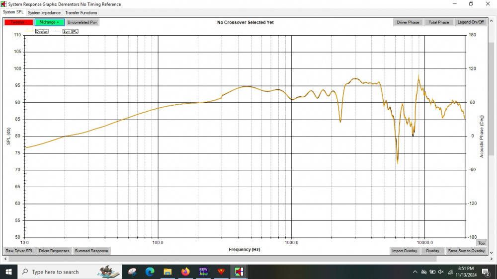
I tried my hand at dual channel measurements with timing reference via REW for the first time. For a sanity check and to ensure my measurements were accurate, I compared my dual channel measurements to the standard 3 measurement method for determining Z offset. What I found is I have to add 6mm of positive (forward) offset to my midrange. When I do that, everything aligns between the dual channel and 3 measurements. This isn't an error with the 3 measurement method because when I perform that same process with the measurements that include the timing reference, I also need to add 6mm positive offset to the midrange to align the summed response.
My question is - is this normal to still need to include some sort of offset with using dual channel measurements? My intuition would be no. But I'm not sure how to troubleshoot what went wrong with the dual channel setup that caused the offset. I presume I need to keep the offset included in the sim when modeling.
Comparison of 3 measurements vs dual channel with 6mm positive offset to midrange

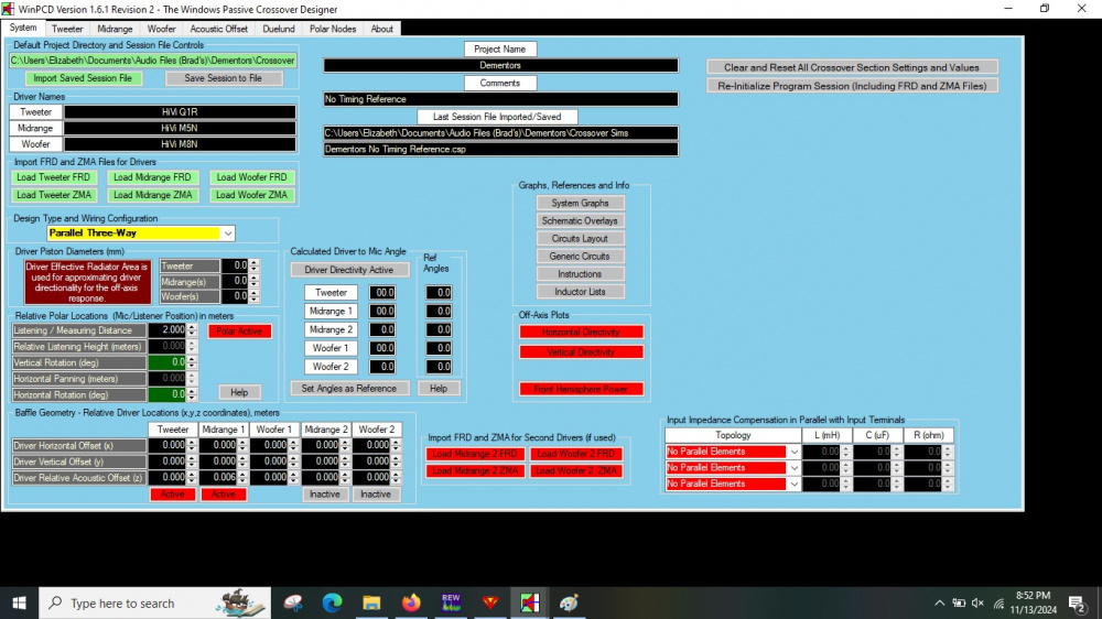
Z offset for dual channel measurements

Z and Y offset for 3 measurement method

Showing 6mm positive offset is needed for 3 measurement method using dual channel measurements for the sim to sum correctly with the measured combined response

Comments
Based on my understanding of how all this stuff works, I would say yes, this is normal. But this is only because you are taking your measurements from a fixed microphone position relative to each driver. The midrange is therefore further away from the microphone tip. This needs to be accounted for. If you were using the standard VituixCAD rules for dual channel measurement, then the microphone position (or driver position) must be raised or lowered for each measurement such that the microphone tip is always the same distance to the driver plane for each measurement. So, in that particular case, no Z offset entry would be needed, only Y offset info.
Oddly this is a 3 way and I don't need to add any Z offset to the midbass, only the midrange. The midbass sums perfectly with no Z offset despite the drivers being further from the mic location.
I also did the VCad measurements where I measured each driver on the driver axis. Once I got a functional crossover with tweeter axis measurements I was going to duplicate the crossover using the driver axis measurements to see if/how they differed.
That is odd. Maybe the phase rotates exactly 360 degrees and therefore appears to need no Z offset (just a guess).
Wait. I need to correct myself. Since time of flight is eliminated with the dual channel setup, there is no phase rotation that needs to be corrected. You should therefore NOT have to add 6mm to align the T+M summed response. This problem came up during Wolf's competition a couple years ago. The supplied FRD's summed properly with zero Z offset because the measurements were done with a dual channel setup.
I have done the process to figure out the z-offset of the midrange in VituixCAD. I didn't need it for crossover work, rather I wanted to know how deep to make a 3D printed waveguide to have the T and M aligned. I did finally get it but the first few tries gave me strange results. I believe the issues were (1) I needed to use minimum phase rather than the actual phase that is available from the dual channel measurements, and (2) the offset is negative in PCD but positive in VituixCAD (if I remember correctly).
I found the thread when this "zero Z offset needed" with dual channel measurements thing was discussed. It was on page 9 of the "indiyana-2022-missing-link-theme-announcement" thread as follows:
https://diy.midwestaudio.club/discussion/1769/indiyana-2022-missing-link-theme-announcement/p9
Minimum phase vs measured phase may be an issue to investigate.
The interesting thing about this offset is I have to set the Z offset for the midrange 6mm closer to the mic (positive in WinPCD, negative in VCad)
Thanks, I'll read that thread
I think I was getting that result too. But it was so long ago I don't remember what all I did before figuring it out.
Mic in same location, properly done 2ch measurement will sum with 0 delay for this process.
Measurements should not be post-processed in any way to affect phase result. Measure, window, export, that's it. REW will include all excess phase regardless of window reference, potentially WinPCD does not process the excess phase well. To remove excess phase and create a more "human readable" phase plot, enter measurement distance as timing offset when measuring, 2.91ms for 1m.
Response shown in first post has suspicious bump at 300Hz, that is shown differently across two screenshots. Recommend processing measurements through VituixCAD for confirmation. Tools -> Aux -> Time Align. Uncheck "MP" boxes, load files and press solve button, delay result should be zero. If zero, then error is in WinPCD. If not zero, then error is in measurement process.
My process was as you describe. So the process itself isn't the problem. So that leaves me figuring out of it's a setting or hardware problem
300hz changes because they are two different measurements. The response in the first screenshot includes the midbass, the last screenshot does not.
WinPCD isn't the problem because I get the same result in VCad. I will however try the process you mentioned and check the results.
Send me your .MDAT file if you can't sort it out.
You can see the VCad process shows the same 6mm forward offset that I found with WinPCD.